What Is A Wire To Wire connection?
This connection type is one of the most common types of connections and is often referred to as an inline wire “Splice”.
Electricity does not discriminated on connection quality and will pass voltage so long as there is a physical link of any size from wire to wire. This creates variability in the quality of various connections because of other factors created as a result of less than adequate connection.
Electrical Resistance and Heat are the two main failures created when a wire to wire connection is done wrong. Imagine a closed system where wire represents a water hose and the electricity is water. A pump on one side pushes water at a set rate. If we squash the hose diameter to half the size, 2 things happen. A) The pump must work harder to push the same water through the half sized hole (resistance) and B) There is a pressure buildup at the location of the squashed hose representing how in an electrical circuit heat builds up when resistance is increased.
These conditions put any circuit at risk of overheating, breakdown of the protective insulating materials and many times results in electrical failure, shorting of voltage to ground due to unprotected wire, and in the worst case, a fire or electrical shock.
With some basic knowledge of how to create a low resistance, high performance wire to wire connection, all of these fallacies can be avoided to create industry standard electrical products.
Below we will look at some of the products, tools and processes commercial wire manufacturers use daily to perform high quality wire to wire connections.
Types Of Splices:
Direct Wire Splice
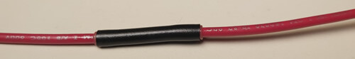
This is the most commonly used splice type in commercial work. It uses solder to fill and solidify the spaces between twisted wire conductors and is then covered with a glued heatshrink product to insulate the connection from outside the circuit.
Step 1: Strip Both wires to be spliced about 1/2″ making sure not a single strand is lost in the stripping process. Specialized hand tools are available to strip wires. These tools range from the cheapest quality at under 10$ up to commercial grade quality that can cost more than 100$.
We prefer to use this Klein Katapult Hand Tool as it is a precision tool and produces high quality repeatable results.
***Step 2: Pre-Apply a glued heatshrink product onto one side of the splice wire
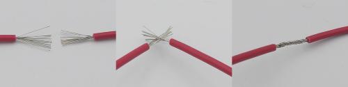
Step 3: Spread the individual conductor strands on both wires apart to create a broom-like splay.
Step 4: Weave the strands together intertwining them and twisting them together into a circular core of combined wire.
Step 5: Place your soldering iron under the connection point and apply solder into the twisted wire strands. Be sure to apply heat and enough solder to see it flow to know that it is a good, solid solder connection
To learn about proper soldering technique, View This Article On Military Grade soldering
Butt Splices
Much like commercial crimping or lugging, butt splices are a crimped solution to attach two or more wires end-to-end. They come in a few different styles and as a result, are used for different applications as well as having different performance characteristics that make them better or worse performing. Butt splices must be selected for the correct gauge of wire to be connected. This means using special connectors when attempting to attach different wire gauges together. Often, a device connected to a power system does not draw enough current to warrant a thicker gauge of wire, but the overall system is higher powered using a larger gauge of wire. In these cases, a special butt splice is used to connect the disparate wires.
Let’s look at the types below:
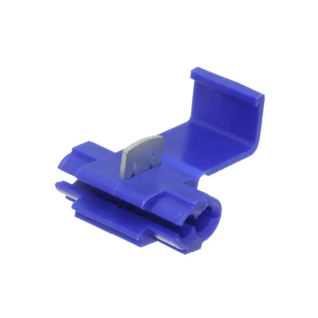
Push down (Scotch Lock)
This is the simplest and cheapest way to attach 2 wires and requires zero knowledge of wire or tooling. It does although come at a disadvantage as far as quality is concerned. These connections are known for allowing intermittent connectivity, they come loose over time, and are generally low quality. We do not suggest this connection type unless you are in a pinch.
Cap Splices
These splices are used when two or more wires end at the same location and require combining. Often 3 or more wires are combined within a cap splice. Cap Splices are applied using mil-spec crimping dies just like commercial CSA & UL certified crimped leads.
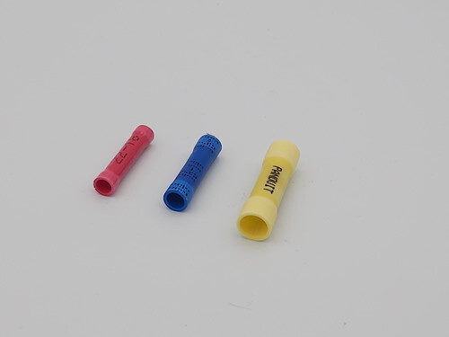
Crimped Butt Splice (The Standard)
The most simple in form, most commonly used to attach two wires end to end. This is the component most likely used in production work because of its ease of application and certified use. End to end crimped butt splices are applied at high speed during production in the same manner as any other commercial crimp. They are certified for use in high voltage applications and are spec’d by gauge.
Solder Sleeve (Splice and Heathshrink combined)
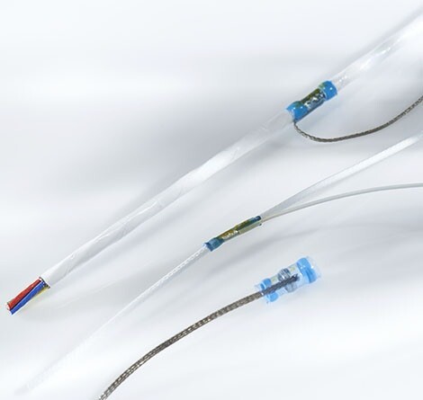
A newer style of splice. This method involves inserting the stripped wire ends into the meltable area of the splice. Heat is applied to the heatshrink to shrink down the outer tubing and solidify the solder to the wire conductors within it. There is little control over the soldering process inside of the tubing creating the possibility of intermittent connections.
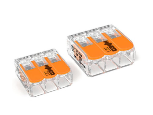
Push on splices
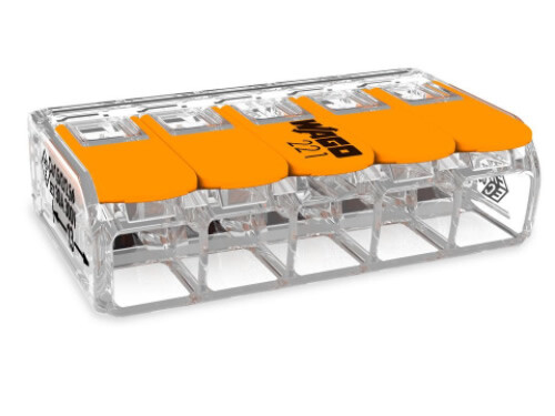
Many solderless splicing solutions exist today, but we will only cover the certified quality ones because there are many uncertified versions with variable quality to the circuits they are used in. This style of splice uses clamping technology to hold the wires in place and create an electrical connection. These certified components specify the strip length to be inserted, are rated for amperage and voltage and have physical pull-out testing characteristics to guarantee circuit quality in commercial work. They can splice a single inline wire and up to 5 conductors into 1 single ended.
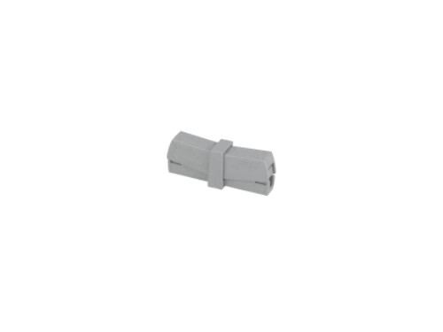
wire to wire
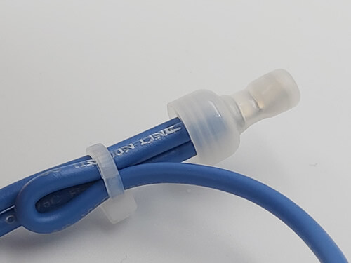
These are an inline version of a push style splice. No tools are required for application, you simply hold the button down, insert the wire conductor, and release. A spring loaded mechanism inside the housing bites into the copper of the wire at a specific strength. The inner surfaces of the clamping material inside the connector are ridged to provide enhanced holding force.
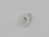
single ended
This is a push on style splice that completes the same task as a crimped cap splice. They are commonly used in installations for aftermarket applications.
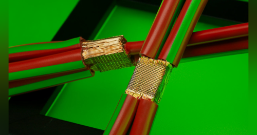
UltraSonic Fusion Splicing
UltraSonic Fusion is a manufacturing process that involves a device which generates a high frequency wave and is then amplified physically during output to a tooling tip. The tip vibrates at the set frequency and power level as two wire ends are placed into its clamping jig. The high speed – high power vibration literally generates melting heat and physically fuses the conductor strands to one another creating a seamless metallic bond.
This process has become the standard method of splicing for all commercial automotive applications.
This technology is also going to become absolutely critical in the high voltage electric car manufacturing industry due to the need for very low resistance contacts. EV manufacturers are finding that typical certified crimped contacts although made to standard are still failing in electric vehicle applications due to the slight voltage drops at high voltage causing overheating of certified connections.
Although the technology has been in use for many years, there is still somewhat of a physics secret as to how the ultrasonic physical booster amplifier operates to amplify the emitted waves. As the technology becomes realized by major markets, costs will be driven down and the technology will surely be public knowledge.
Found this article helpful? Share it below!